Want to be notified of information like this? Become an ECD Insider and be in the know first.
The Impact of Thermocouple Attachment Methods on Thermal Profiling Accuracy
By Mark Waterman, Mike Hayward, and Oscar Gomez, ECD
High-reliability electronics manufacturing relies heavily on thermal profiling to ensure reflow soldering process parameters are correctly determined and maintained during printed circuit board (PCB) production.
Establishing the correct thermal profile to meet solder paste specifications, component constraints, and equipment
capabilities involves the measurement of a product sample. To capture specific temperature measurements, thermocouples are attached at strategic points on the PCB and are connected to a thermal profiler that records the data. Measurements are taken, and any required machine setting adjustments are made until satisfactory results are achieved. This may take one profiling operation or several attempts before the specification is reached.
Though process control methods for specification adherence can take many forms, the most common
approach is repeated thermal profiling of the product sample used in the initial setup. The product sample is often referred to as the “Golden Sample” or the “Golden

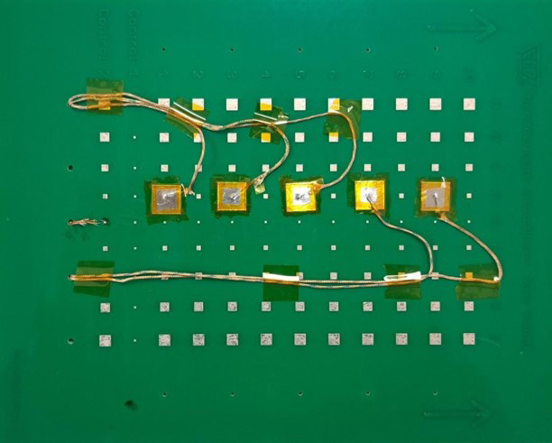
Figure 1: test vehicle
(aluminum tape attachment).
Board” and is re-measured periodically, and results are compared to the baseline profile initially established.
Achieving and maintaining accurate temperature readings is vital at both the initial product profile
and subsequent verification profiles. Precise temperature measurements are largely influenced by the method of thermocouple attachment, underscoring the importance of an attachment using a medium that ensures accuracy. Direct surface-to-surface contact between the measured solder pad and thermocouple tip is vital. Thermal conductivity should be maximized between the two surfaces and minimized at the mass around the connection.
Mechanically, the interface needs to be strong enough to ensure the thermocouple does not detach throughout the reflow soldering process and, in the case of a “Golden Sample,” can withstand storage, handling, and several passes through the process over several months (or even years).
Thermocouple Attachment
There are several thermocouple attachment methods currently used in the electronics industry. A recent study set out to better understand the accuracy performance of each of them, draw comparisons, and establish which method performs best against the criteria stated above.
A set of experiments was designed specifically to analyze the following thermocouple attachment methods: high-temperature solder; polyamide (Kapton) tape;
aluminum tape; UV-cured adhesive; and low-temperature cure surface-mount (SMD) adhesive.
A PCB was designed and manufactured with an array of solder pads of differing sizes consistent with a typical SMT product. Holes were included in the PCB to allow for routing and wire stress relief. Thermocouples were attached to points on the PCB using each of the attachment methods listed above. A new PCB was used for every measurement and a control thermocouple, employed to provide a baseline, was attached to the same 1.0 mm pad on every PCB using high-temperature solder (Figure 1).
A reflow soldering oven was set up to produce a typical lead-free solder profile. No changes to the machine parameters were made during the experiments, and a capability study using 30 sample boards was conducted to ensure the settings were stable and repeatable. The peak temperature of the control pad, with the thermocouple tip attached using high-temperature solder, returned an average temperature of 257.8°C with a standard deviation of 0.5°C.
Cp and Cpk values of 1.0 were reported with upper and lower control limits of three standard deviations (+/-1.50°C). Based on these results, the test procedure was deemed valid (Figure 2).
All attachment types, except for the UV adhesive, offered good mechanical strength with no detached thermocouples recorded. The UV adhesive suffered four detachments throughout the 11 cycles, making it difficult to collect any meaningful data for the comparison tests. Therefore, this evaluation suggests that UV adhesive may not be a viable attachment method.
All other attachment types returned lower values. The following tables illustrate and quantify the deviations.
Figure 4 shows that all control thermocouple measurements fall within the required limits. This is also true of all readings where high-temperature solder is the attachment method. Notice the reduction in measured temperature with Kapton tape, aluminum tape, and SMD adhesive. This indicates that the attachment method may interfere with the thermocouple/solder pad interface. It is likely that the mass of the tape/adhesive is the cause. As discussed above, the UV adhesive results are inconclusive, as two thermocouples became detached.

Figure 2: control thermocouple capability study chart.

Figure 3: attachment method processing order.
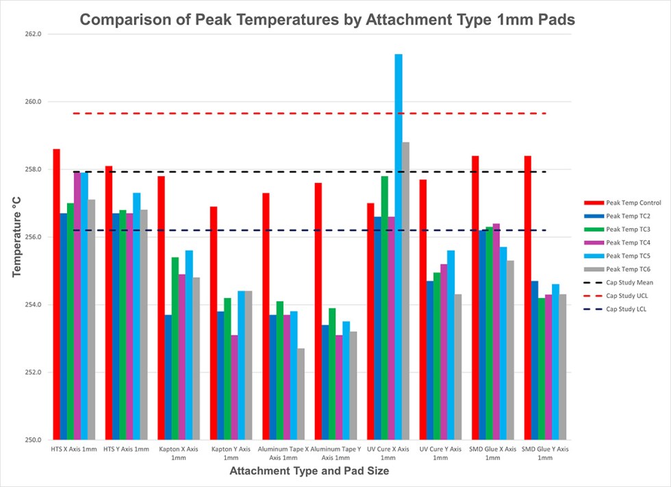
Figure 4: peak temperature comparison by type, 1 mm pads.

Figure 5: peak temperature comparison by type, 5 mm pads.

Figure 6: quantified deviation from capability study x-bar.
Figure 6 quantifies the average deviation experienced for each attachment method. (Again, the UV adhesive results should be disregarded as the readings are influenced by the detachments experienced during the trial.)
These temperature readings suggest that hightemperature solder provides strong mechanical and thermal bonds between the thermocouple and the tested area, and it returns the most accurate results. All other methods delivered temperatures well outside the required specification for accuracy and this should be considered when choosing an attachment medium.
Tests 3 and 7-11 were conducted using the same PCB to study the repetitive use of a “Golden Sample.” The results showed that measured values decreased significantly with each cycle.
Based on the outcomes of this analysis, one could conclude that a “Golden Board” should not be used more than ten times, as there is a significant risk that measured values will fall out of tolerance purely from overuse (Figure 7).
Conclusion
In addition to the thermal profiler instrument’s capability, the method of thermocouple attachment has a significant influence on the accuracy of temperature
readings. This analysis suggests that high-temperature solder is the most reliable attachment medium. Likewise, overuse of a product sample, or “Golden Board”, may result in deterioration of temperature reading accuracy, and this study demonstrates that a limit of ten runs per sample should be considered. Finally, it should be noted that each attachment method’s quality may also impact adhesion and measurement, so future studies should consider multiple suppliers of each material used for thermocouple attachment.

Figure 7: repetitive testing — degradation of measured values.