|
Prior to any maintenance or service on this unit, disconnect the power cord from the power supply. Before reattaching the unit to its power supply, be sure all covers and the fastening hardware are in place and secure. |
.png "Warning")
10.1 Cleaning
The interior and exterior of the ECD SmartDRY™ Cabinet can be cleaned as desire using mild soap and water. DO NOT use chlorine-based bleaches, abrasive, volatile or flammable cleaners.
|
Both sides of the door glass are protected with a special ESD film. This film is very sensitive to abrastions and must be cleaned only per the recommended methods. |
Before cleaning, certain precautions need to be taken:
•ALWAYS disconnect the cabinet from the power cord from the power supply when cleaning the interior.
•Use a non-abrasive cloth or soft tools such as plastic brushes. DO NOT USE hard tools such as metal wire brushes or steel wool.
•Wipe dry with a soft cloth.
10.2 ECD SmartDRY™ Humidity and Temperature Sensor
This sensor is a highly accurate environmental sensors. Exposing the sensor to the following can cause drift of the humidity reading – irreversibly in most cases. The list below are examples and do not represent a complete list of possible harmful substances, but are the most common used in electronic manufacturing.
Do not allow the sensor to be exposed to:
•Solvents or other organic compounds including: Ketenes, Acetone, Ethanol, Isopropyl Alcohol, Toluene, etc.
•Acids and bases including: HCl, H2SO4, HNO3, NH3 etc.
•Ozone in high concentration or H2O2
•Cleaning agents or strong air blasts from an air-gun.
|
Please note that such chemicals are contained in uncured epoxies, glues, adhesives, etc. and outgas during baking and curing. Do not use the ECD SmartDRY™ Cabinet as a curing chamber for these processes. These chemicals are also added as plasticizers in plastics, used for packaging materials, and may also out gas for some time. Only allow well cured approved Moisture Barrier Bag to be use in the Cabinet. |
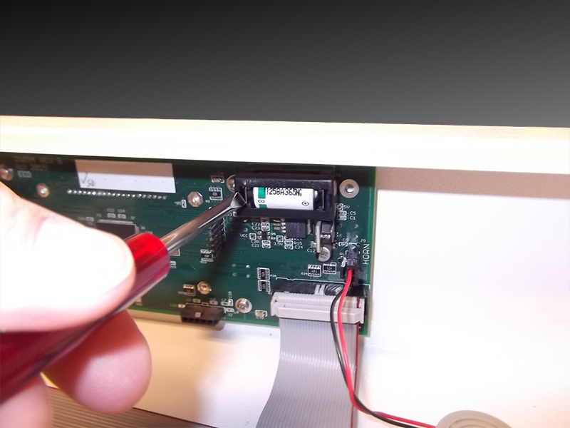
10.3 Clock Battery
The real time clock is battery backed and will require replacement at least annually or more often if there have been long or total accumulative power outages.
To change the battery please follow these steps:
| 1) | ALWAYS disconnect the cabinet from the power cord from the power supply before replacing the battery. |
| 2) | Remove the control chassis top cover screws located on the cover’s back. |
| 3) | Slide the cover back about 20mm (1”) and lift off the top. Be careful to prevent the cover from falling inside the control chassis. |
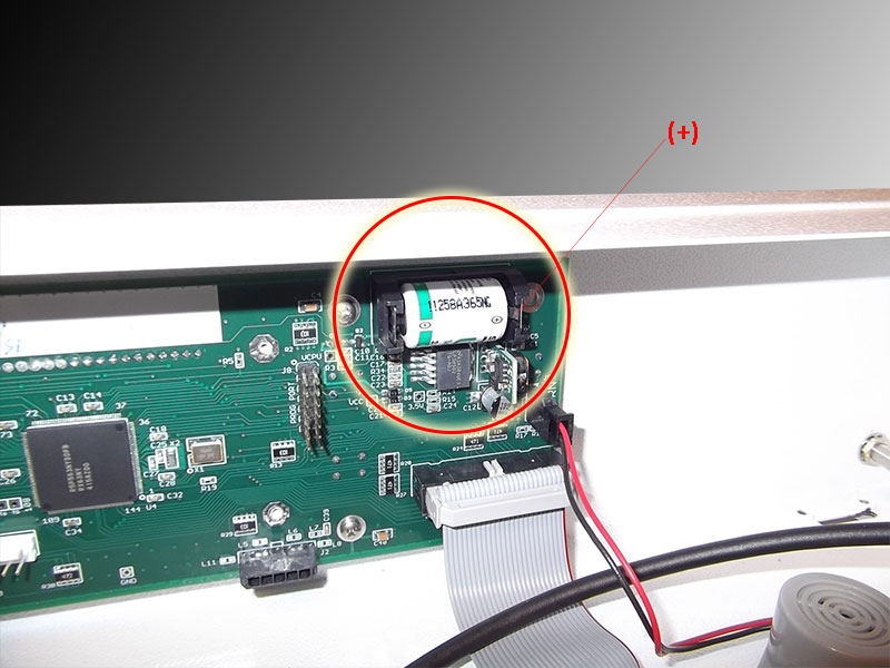
| 4) | Locate the battery on the Main Board. Remove the battery retainer and old cell. To remove the battery retainer, slide a small screw driver or similar too, between the battery. Replace the cell with a 3.6V 1.2Ah cell, LS14250 (ANSI 1/2AA, IEC 1/2R6) by Saft or equivalent. Note the battery polarity as you install the new cell. Refer to Section Appendix B: Parts List for reordering information. |
|
|
| 5) | Replace the top cover and the fastening hardware BEFORE connecting the power cord to the power supply. |
10.4 ECD SmartDRY™ Dryer
The ECD SmartDRY™ Dryer module should last for many years and yet is designed to be replaced, should damage occur or a component fails. ECD SmartDRY™ will warn if a Dryer loses it's effectiveness for any reason.
|
PRIOR TO DRYER REPLACEMENT, THE VERSION OF DRYER MODULE THAT IS INSTALLED ON YOUR CABINET MUST BE IDENTIFIED. THIS CAN BE DONE BY A QUICK INSPECTION OF THE DRYER CABLE CONNECTOR.
|
.png "Important Information")
.png)
.png)
To change the Dryer please follow these steps:
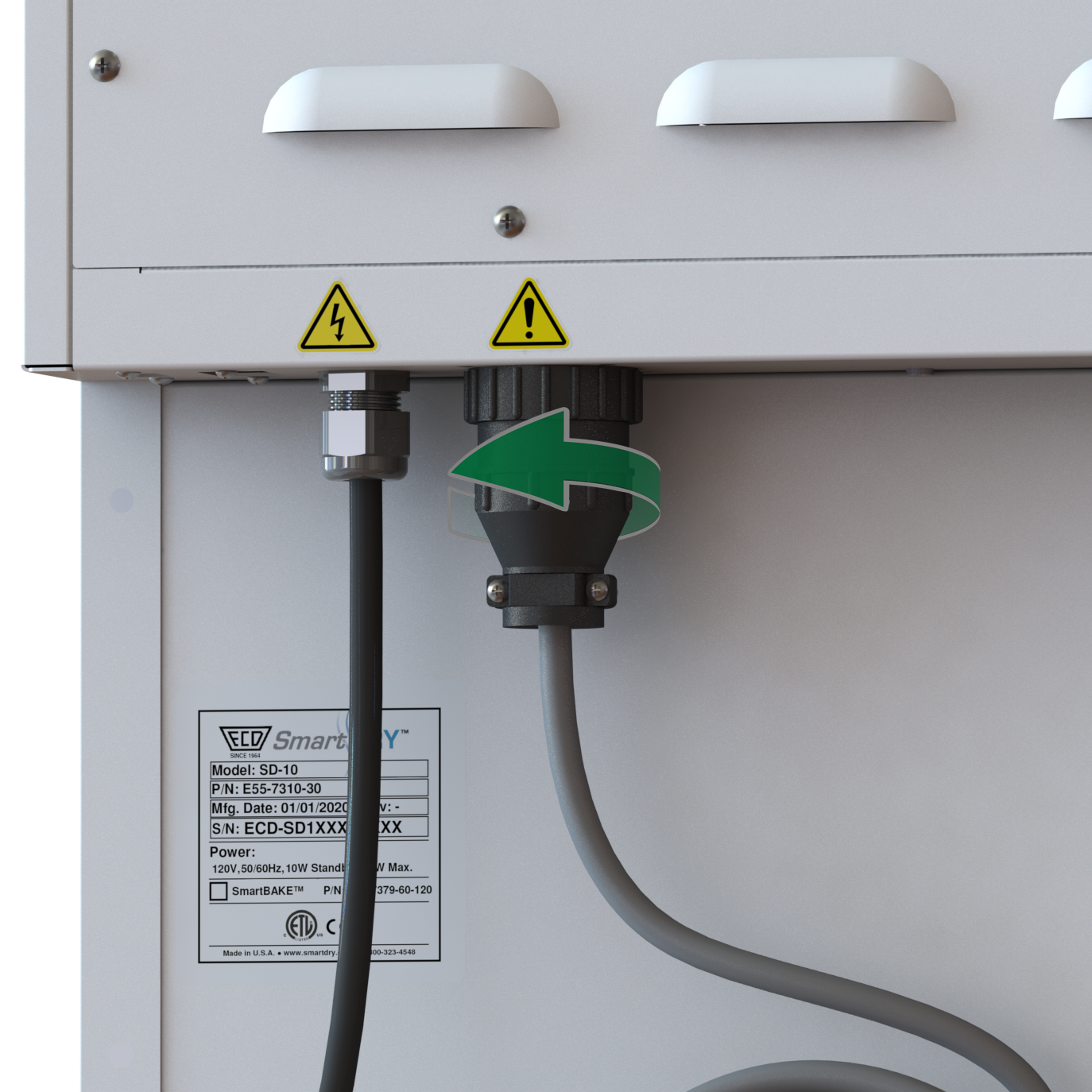
| 1) | ALWAYS disconnect the cabinet from the power cord from the power supply before replacing the Dryer. |
| 2) | Disconnect the Dryer cable from the control chassis by turning the lock collar 1/4 turn counter clockwise. |
10.5 Power Board
|
Prior to any maintenance or service on this unit, disconnect the power cord from the power supply. Before reattaching the unit to its power supply, be sure all covers and the fastening hardware are in place and secure. |
Step 1 - Disassemble:
|
The Power Board has capacitors which can remain charged. Handle board from the edges only. |
| 1) | Remove the control chassis top cover. |
•Remove the 4 to 6 screws (model dependent) on the back of the top cover.
•Slide the top cover back about 2 cm (1/2”).
•Lift up and disconnect light tower option, if included.
•Place top cover aside.
|
Connectors with a locking latch must have the latch pressed while carefully pulling the connector. |
| 2) | Disconnect all wire harnesses from Power Board. |
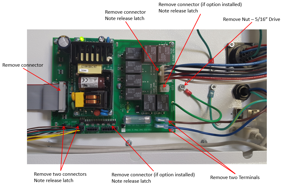
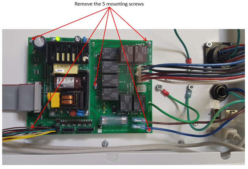
| 3) | Remove 5 mounting screws from the four corners and center of board and set board aside. |
Step 2 - Replace the Power Board:
| 1) | Place the new Power Board onto the standoffs. Note the board’s orientation. |
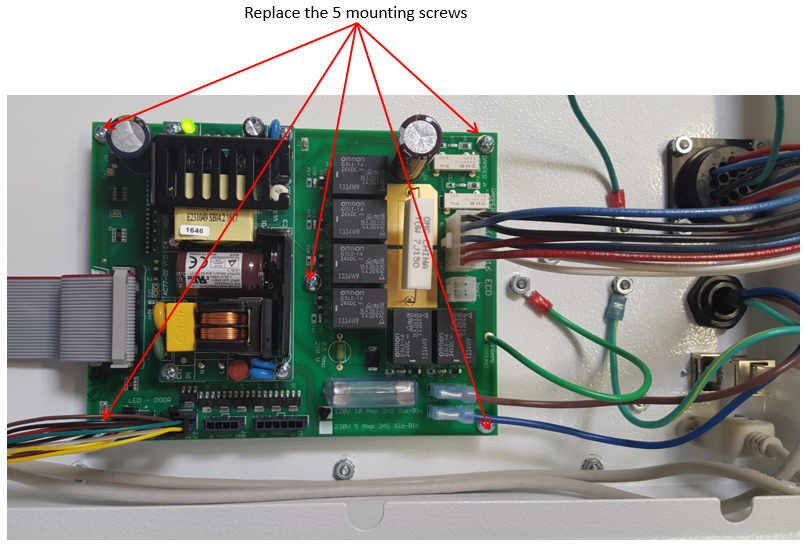
| 2) | Replace the 5 mounting screws on the four corners and center of board. |
| 3) | Reconnect all the wire harnesses. Connectors with the latch will “snap” into place when the connector is correctly seated. |
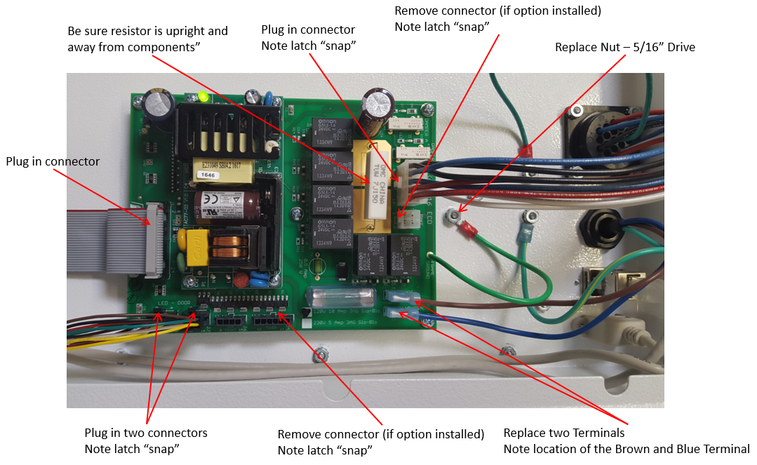
|
Make sure large resistor is upright away from components. |
Step 3 - Final Assembly:
| 1) | Replace the top cover: |
•Lower the top cover and connect light tower option to J5 on Power Board, if included.
•Set the cover into the top slots.
•Slide the top cover forward about 2 cm (1/2”) to lock down in place.
•Replace the 4 to 6 screws (model dependent) on the back of the top cover.
| 2) | Connect power to test. |
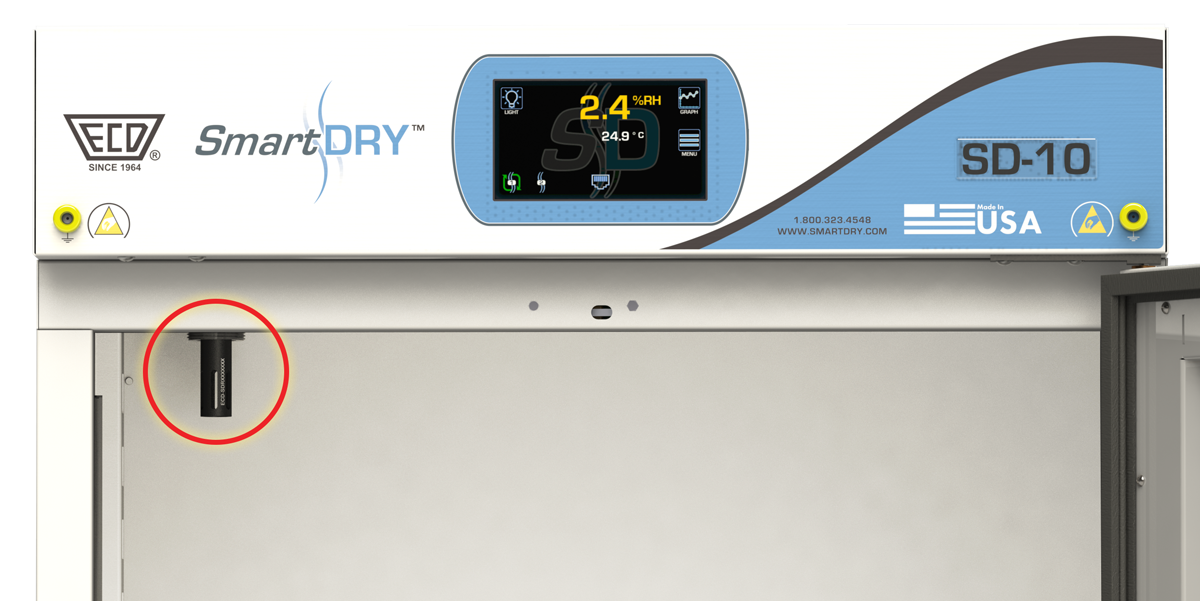
10.6 RH/Temperature Probe
The RH/Temperature probe should be calibrated on a regular basis. A good calibration schedule is annually, however your calibration practices may be different. The probe can only be calibrated by ECD and can be easily removed and returned. Because the calibration information is kept internal to the probe, a replacement probe can be purchased and “swapped” when it comes time to calibrate.
To remove and or swap the RH/Temperature probe, please follow these steps:
| 1) | ALWAYS disconnect the cabinet from the power cord from the power supply before replacing the probe. |
| 2) | Remove the control chassis top cover screws located on the cover’s back. |
| 3) | Slide the cover back about 20mm (1”) and lift off the top. Be careful to prevent the cover from falling inside the control chassis. |
| 4) | Find the probe in the back left corner of the control chassis and press the plug release lock and carefully disconnect the probe cable. |
|
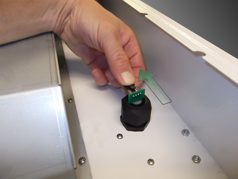
| 5) | Loosen the probe locking collar by turning it counter clockwise and lift out the probe. |
| 6) | Lower the replacement probe into the locking collar and secure by turning the collar clockwise. Finger tight is all that is needed. |
| 7) | Reconnect the cable making sure the orientation is correct and the release lock latches into place. |
| 8) | Replace the top cover and the fastening hardware BEFORE connecting the power cord to the power supply. |
| 9) | Return the Probe for calibration by obtaining an RMA number on the ECD website or calling ECD Service at 1-800-323-4548. Refer to section 11.0 Service and Troubleshooting for additional information. |
10.7 SmartBAKE™ Heater
The SmartBAKE™ heater module should last for many years and yet is designed to be replaced, should damage occur or a component fails. ECD SmartDRY™ warns if the Bake cannot heat for any reason.
To change the heater module, please follow these steps:
| 1) | ALWAYS disconnect the cabinet from the power cord from the power supply before replacing the heater module |
| 2) | Remove the control chassis top cover screws located on the cover’s back. |
| 3) | Slide the cover back about 20mm (1”) and lift off the top. Be careful to prevent the cover from falling inside the control chassis. |
| 4) | Disconnect the heater cable from the power board by press the plug release lock and carefully unplug. |
|
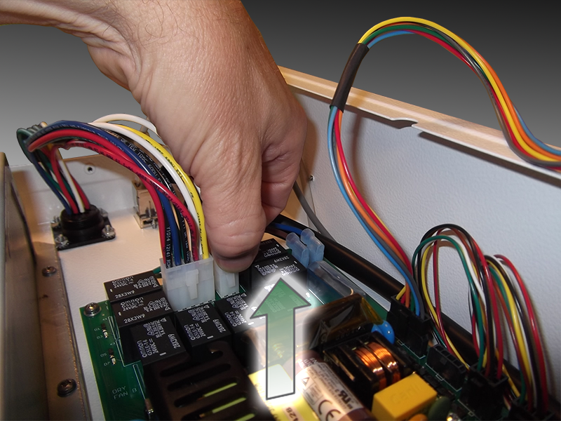
| 5) | Remove the 6 mounting screws that secure the heater to the top and lift out the heater module. 4 on the sides and front. 2 on the rear. |
.jpg)
| 6) | Place the replacement heater into place, making sure the output plenum fits down inside the back vent plenum. |
|
| 7) | Replace the 6 mounting screws that secure the heater to the top panel. |
| 8) | Reconnect the heater cable to the Power board making sure the orientation is correct and the release lock latches into place. |
| 9) | Replace the top cover and the fastening hardware BEFORE connecting the power cord to the power supply. |
| 10) | Reconnect the power plug to the power source. |
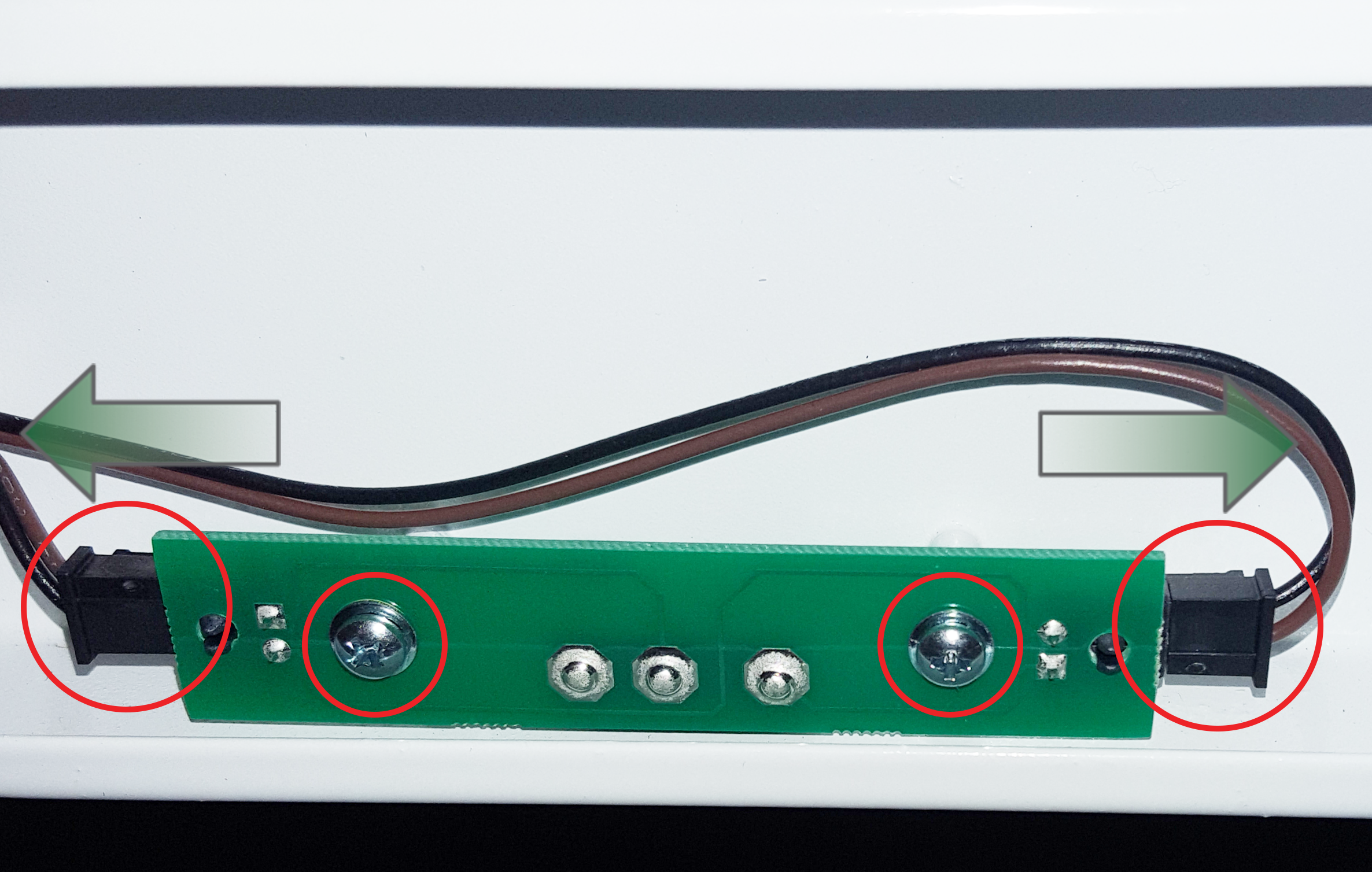
10.8 Door Switch
To replace a Door Switch, please follow these steps:
| 1) | ALWAYS disconnect the cabinet from the power cord from the power supply. |
| 2) | Open the door closest to the door switch being replaced. |
| 3) | From the inside of the cabinet, remove the 2 hardware screws. |
| 4) | Press the plug release locks and carefully disconnect the cables. |
|
| 4) | Reconnect the cables making sure the release lock latches into place. |
| 5) | Re-mount the door switch with the 2 hardware screws. Make sure the door switch lever does not protrude out of the switch slot. If it does the board will need to be re-mounted. |
|
|
.png)
.png)
| 6) | Reconnect the power plug to the power source. |
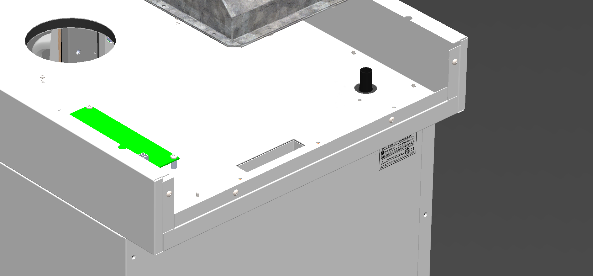
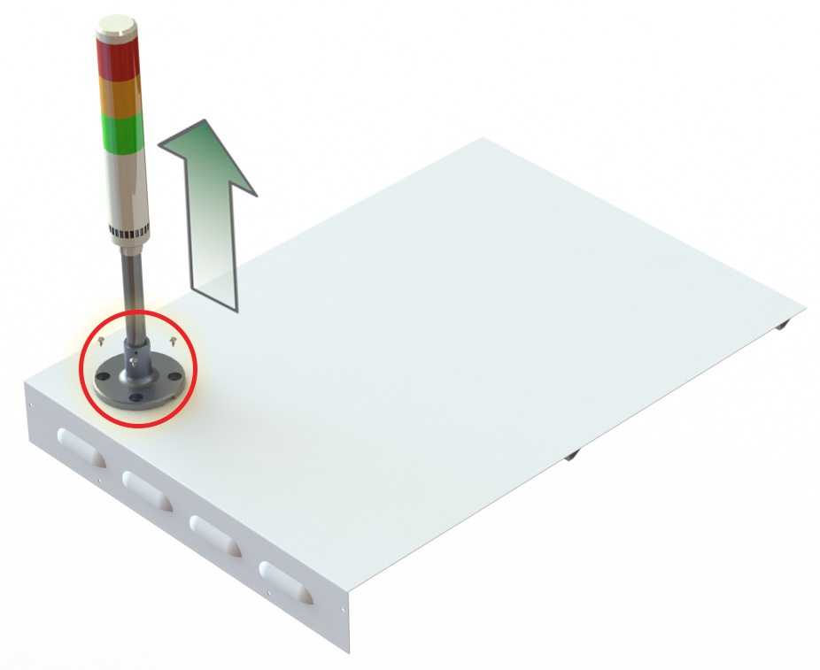
10.9 LIGHT TOWER REPLACEMENT
To remove a Light Tower:
| 1) | ALWAYS disconnect the cabinet from the power cord from the power supply. |
| 2) | Remove the 4 to 6 screws (model dependent) on the back of the Cabinet Cover. |
.png)
| 3) | Slide the Cabinet Cover back about 2 cm (1/2”) and then tilt to up disconnect Light Tower from the Power Board. |
.png)
| 4) | Set the Control Cover aside on a flat surface. |
| 5) | Remove the hardware screws from the bracket. Pull the Light Tower and bracket off of the Control Cover. |
To install:
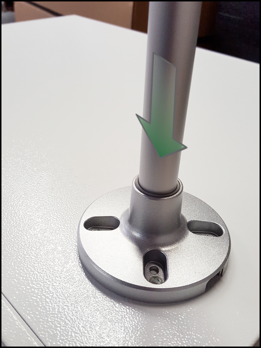
| 1) | Remove any packaging. |
| 2) | Slide the Light Tower cable thru the Control Cover and mounting bracket until the metal post of the light tower is fully seated into the bracket. |
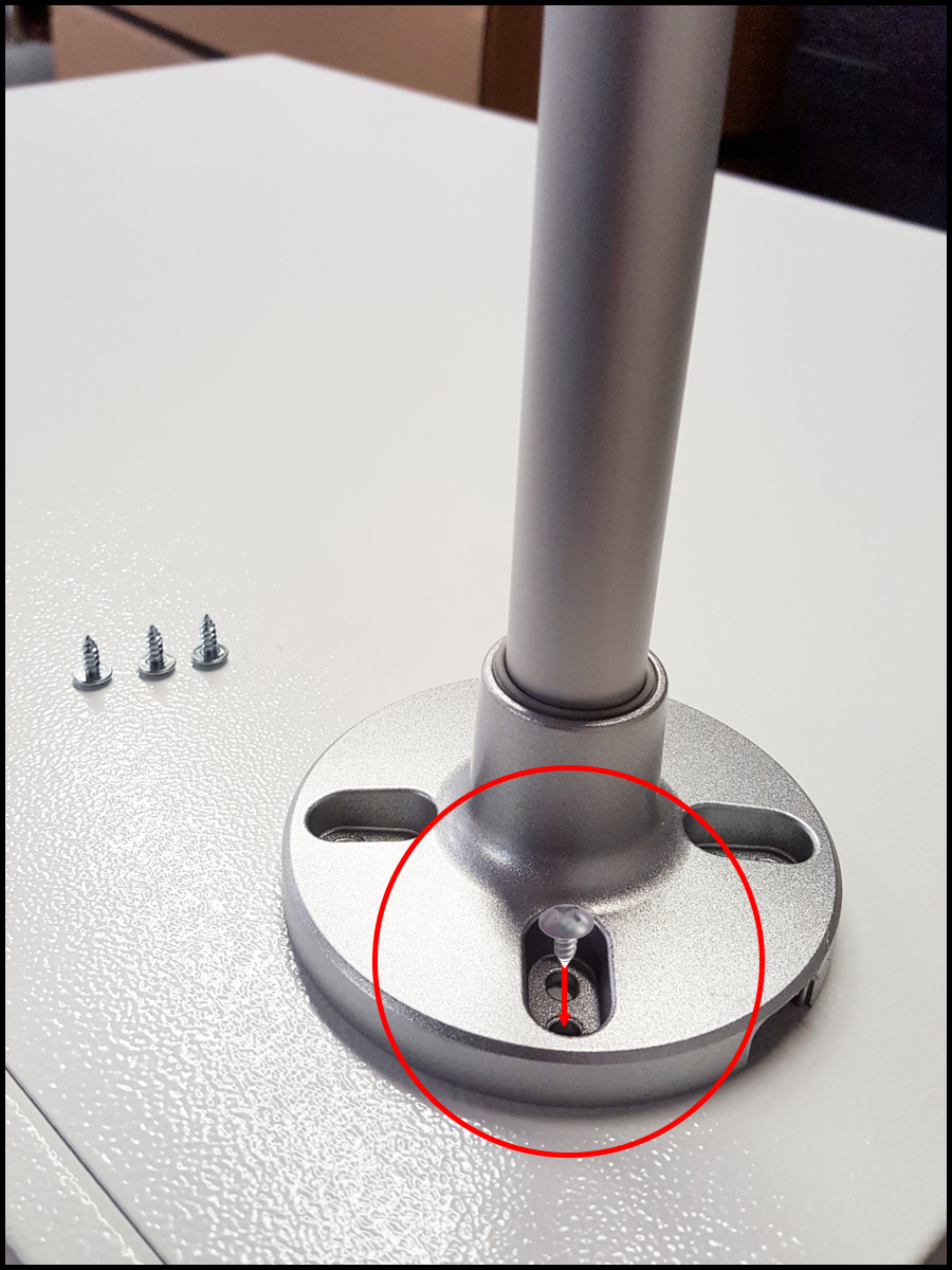
|
IF YOU WANT TO SECURE THE LIGHT TOWER TO THE MOUNTING BRACKET, REMOVE THE BRACKET FROM THE CONTROL CHASSIS COVER AND MOUNT THE BRACKET TO THE LIGHT TOWER WITH THE PROVIDED SCREWS.
|

| 3) | Re-mount the light tower to the control chassis cover with four self tapping sheet metal screws (#6 x 3/8"). |
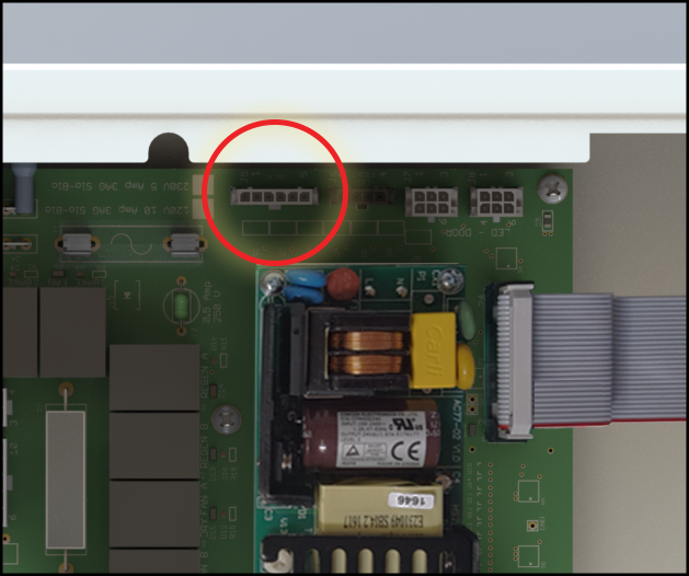
| 4) | Plug the Light Tower into the Power Board. |
| 5) | Slide the Control Cover back into place and secure with the cover screws. |
| 6) | Reconnect the power plug to the power source. |