Appendix A: Parts List
Accessories:
Description |
Part Number |
|---|---|
SD-10 & SD-30 Fixed Shelf Kit |
E56-7379-23 |
SD-10 & SD-30 Fixed 7" Reel Rack Kit |
E56-7379-23-107 |
SD-10 & SD-30 Fixed 7"/15" Combo Reel Rack Kit |
E56-7379-23-175 |
SD-10 & SD-30 Pull-out Shelf Kit |
E56-7379-23-200 |
SD-10 & SD-30 Pull-out 7" Reel Rack Kit |
E56-7379-23-207 |
SD-10 & SD-30 Pull-out 7"/15" Combo Reel Rack Kit |
E56-7379-23-275 |
SD-48F Fixed Shelf Kit |
E55-7483-23 |
SD-48F Pull-out Shelf Kit |
E56-7483-23-200 |
Cabinet Light Tower |
E55-7379-74 |
Combination Door Locks |
P57-7850-34 |
Recommended Replaceable Parts:
Description |
Part Number |
|---|---|
RH/Temperature Probe (ECD) |
E56-7379-25 |
Fuse (120VAC): 10Amp Slo-Blo 3AG |
F00-0026-20 |
Real Time Clock Backup Battery |
F30-0048-00 |
Replaceable Parts:
Description |
Part Number |
|---|---|
Main Controller Board |
|
Power Board |
|
Door Switch |
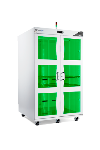
Appendix B: Specifications
|
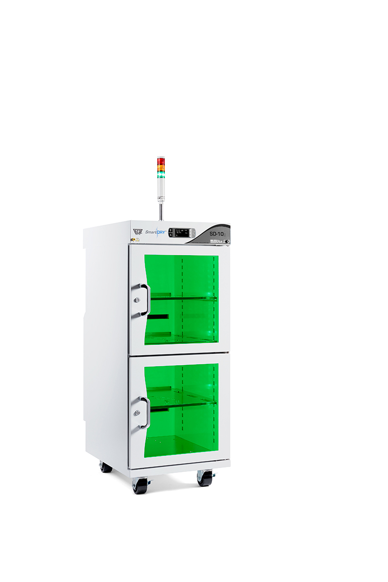
SD-10 E55-7310-30/35 |
SD-10SB E58-7310-60/65 |
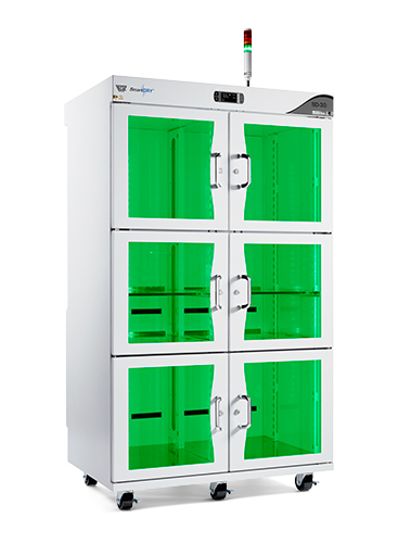
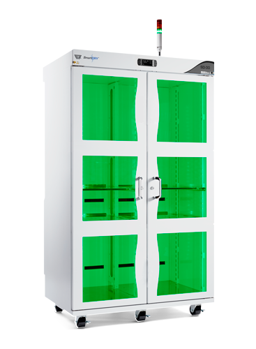
SD-30 E55-7330-30/35 |
SD-30XD E57-7339-30/35 |
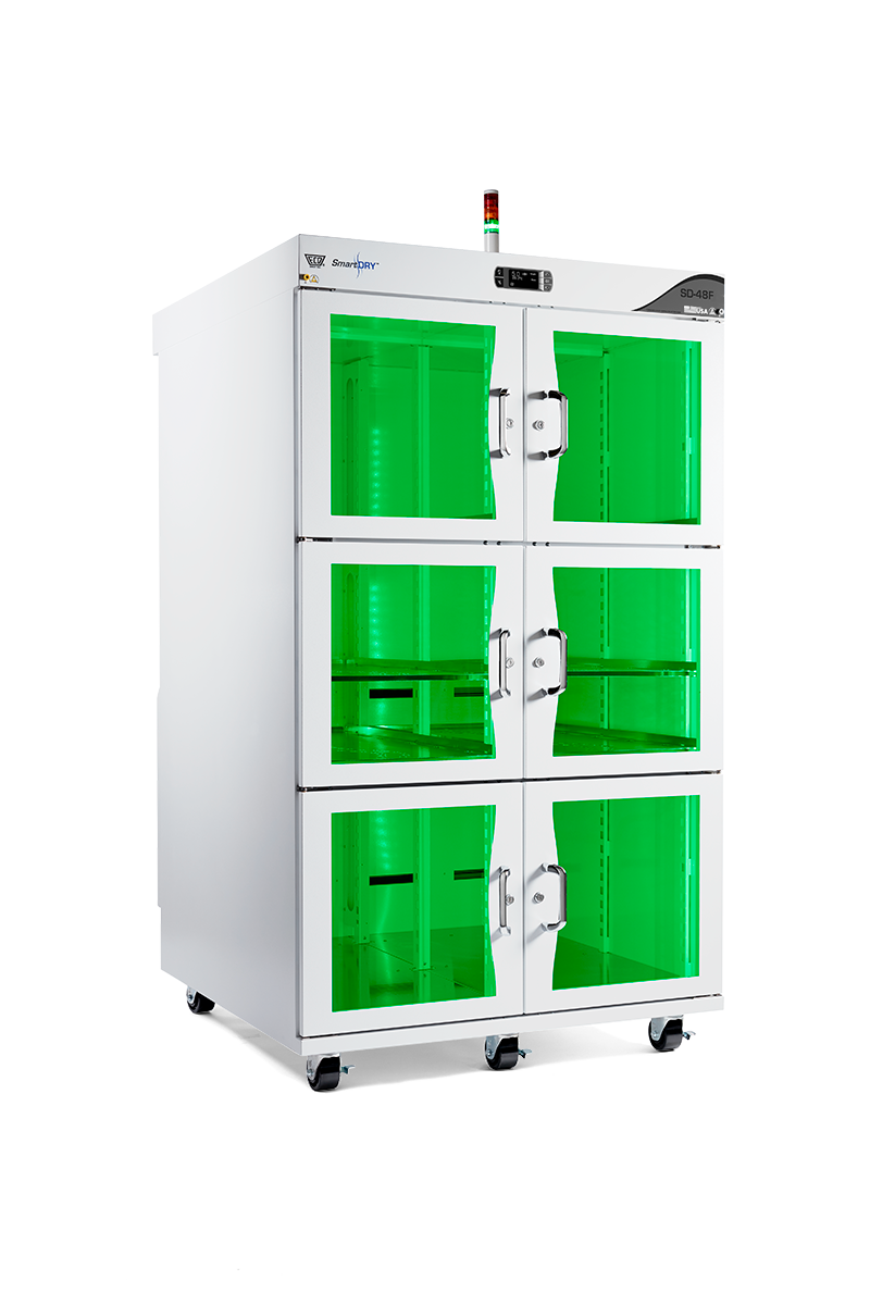
SD-48F E55-7483-30/35 |
SD-48FXD E57-7489-30/35 | N/A | N/A |
|---|---|---|---|---|---|---|
|
|
|
|
|
|
|
Recovery*: |
||||||
Suggest Interval of cabinet access |
12/hour |
12/hour |
12/hour |
12/hour |
10/hour |
10/hour |
Recovery to <5% |
3 minutes |
3 minutes |
4 minutes |
4 minutes |
5 minutes |
5 minutes |
Recovery to set point from opened door |
3 minutes |
3 minutes |
4 minutes |
9 minutes |
5 minutes |
9 minutes |
* Recovery tested at 50%RH @ 25°C |
||||||
Doors & Shelving: |
||||||
Number of Doors |
2 |
2 |
6 |
2 |
6 |
2 |
Magnetic Door Seals |
Yes |
Yes |
Yes |
Yes |
Yes |
Yes |
ESD Safe |
Yes |
Yes |
Yes |
Yes |
Yes |
Yes |
Number of Shelves |
1 Floor Shelf |
1 Floor Shelf |
2 Floor Shelves |
2 Floor Shelves |
2 Floor Shelves |
2 Floor Shelves |
Adjustable Shelves |
Yes |
Yes |
Yes |
Yes |
Yes |
Yes |
Additional Shelves Available |
Yes |
Yes |
Yes |
Yes |
Yes |
Yes |
Max Load Capacity per Shelf |
22 kg (50 lbs) |
22 kg (50 lbs) |
22 kg (50 lbs) |
22 kg (50 lbs) |
22 kg (50 lbs) |
22 kg (50 lbs) |
Casters |
76.2 mm (3") diameter |
76.2 mm (3") diameter |
76.2 mm (3") diameter |
76.2 mm (3") diameter |
76.2 mm (3") diameter |
76.2 mm (3") diameter |
Weight & Dimensions: |
||||||
External Dimension (HxWxD) |
1143 mm x 508 mm x 762 mm (45” x 20” x 30”) |
1143 mm x 508 mm x 762 mm (45” x 20” x 30”) |
1778 mm x 1016 mm x 762 mm (70” x 40” x 30”) |
1778 mm x 1016 mm x 762 mm (70” x 40” x 30”) |
1778 mm x 1016 mm x 1194 mm (70” x 40” x 47”) |
1778 mm x 1016 mm x 1194 mm (70” x 40” x 47”) |
Internal Dimension (HxWxD) |
985 mm x 479 mm x 540 mm (38.8” x 18.8” x 21.2”) |
985 mm x 479 mm x 540 mm (38.8” x 18.8” x 21.2”) |
1500 mm x 990 mm x 540 mm (59” x 38.9” x 21.2”) |
1500 mm x 990 mm x 540 mm (59” x 38.9” x 21.2”) |
1500 mm x 990 mm x 914 mm (59” x 38.9” x 36”) |
1500 mm x 990 mm x 914 mm (59” x 38.9” x 36”) |
Weight |
< 70kg (155 lbs) |
< 70kg (155 lbs) |
< 163 kg (360 lbs) |
< 163 kg (360 lbs) |
<211kg (464 lbs) |
<211kg (464 lbs) |
Internal Capacity |
283 liters (10 cu ft) |
283 liters (10 cu ft) |
850 liters (30 cu ft) |
850 liters (30 cu ft) |
1360 liters (48 cu ft) |
1360 liters (48 cu ft) |
Construction: |
||||||
Country of Manufacturing |
USA |
|||||
External & Internal |
ESD powder coated steel |
|||||
Power: |
||||||
Voltage |
120V +/-10%, 50/60Hz |
120V +/-10%, 50/60Hz |
120V +/-10%, 50/60Hz |
120V +/-10%, 50/60Hz |
120V +/-10%, 50/60Hz |
120V +/-10%, 50/60Hz |
Power Consumption |
10W Standby, 450W Max., |
10W Standby, 450W Max., |
25W Standby, 850W Max., |
25W Standby, 850W Max., |
25W Standby, 850W Max., |
25W Standby, 850W Max., |
Power Input |
Standard US Plug 120VAC 60Hz |
Standard US Plug 120VAC 60Hz |
Standard US Plug 120VAC 60Hz |
Standard US Plug 120VAC 60Hz |
Standard US Plug 120VAC 60Hz |
Standard US Plug 120VAC 60Hz |
Desiccant |
||||||
Zeolite |
4A Molecular Sieve |
|||||
Projected Life of desiccant |
7+ years |
|||||
Number of dehumidifiers |
2 |
2 |
4 |
4 |
4 |
4 |
Internal RH Capability |
0.5 %RH |
|||||
RH and Alarms |
||||||
Display Resolution (RH/Temp) |
0.1% / 0.1˚C (0.1˚F) |
|||||
Accuracy (RH/Temp) |
± 1.8% / ± 1˚C (1.8˚F) |
|||||
Calibration |
User replaceable probe, 1 Year calibration interval recommended. |
|||||
Standard Alarms |
SmartDRY™: Over RH & Over Temperature |
SmartDRY™ & SmartBAKE™: Over RH & Over Temperature |
SmartDRY™: Over RH & Over Temperature |
SmartDRY™: Over RH & Over Temperature |
SmartDRY™: Over RH & Over Temperature |
SmartDRY™: Over RH & Over Temperature |
ESD Safety: |
||||||
ESD Control |
ESD20.20/IEC 61340-5-1 |
|||||
Paint and Glass Surfaces |
Surface resistance <=1x10^8 Ohms/square |
|||||
Wrist Strap Ground |
2 |
|||||
Earth Ground Points |
Ground point and Drag chain |
|||||
Environmental: |
||||||
Temperature |
15˚C-35˚C |
|||||
Humidity |
10%-80% |
|||||
Altitude |
<2,000 Meters (6,561ft) |
|||||
Location |
Indoor Only |
|||||
Appendix C: Schematic
MODEL SD-10 & SD-10SB:
.png)
MODEL SD-30, SD-30XD, SD-48F & SD-48FXD:
.png)
Appendix D: Useful Tables
Bake times required to reset floor life |
|||
Bake time (days) at 40C |
|||
Package Body Thickness |
MSL # |
Exceeding Floor Life >72 Hours |
Exceeding Floor Life <=72 Hours |
<=1.4mm |
2 |
8 |
5 |
2a |
9 |
7 |
|
3 |
13 |
9 |
|
4 |
15 |
9 |
|
5 |
17 |
10 |
|
5a |
22 |
10 |
|
>1.4mm & <=2.0mm |
2 |
25 |
20 |
2a |
29 |
22 |
|
3 |
37 |
23 |
|
4 |
47 |
28 |
|
5 |
57 |
35 |
|
5a |
79 |
56 |
|
>2.0mm & <=4.5mm |
2 |
79 |
67 |
2a |
79 |
67 |
|
3 |
79 |
67 |
|
4 |
79 |
67 |
|
5 |
79 |
67 |
|
5a |
79 |
67 |
|
Moisture Classification Level and Floor Life, J-STD-033, 5.2 |
|
Moisture Sensitivity Level |
Floor Life (out of bag) at factory ≤30 ºC/60% RH |
1 |
Unlimited at ≤30 ºC/85% RH |
2 |
365 days |
2a |
28 days |
3 |
7 days |
4 |
3 days |
5 |
2 days |
5a |
1 day |
6 |
Mandatory bake before use. After bake, must be soldered within the time limit specified on the label. |
AppendiX E: Gossary
Relative Humidity (%RH):
The amount of water vapor currently in the air divided by the maximum amount of water vapor the air could hold at that same temperature multiplied by 100, expressed in percent. Cold air cannot hold very much water vapor, and hot air can hold much more. In fact, 5°C air at 100% relative humidity holds only 6.8 grams. This means that at 5°C, air will go from 0% RH to 100% RH by adding (evaporating) only 6.8 grams if water. At 25°C it takes 23 grams of water to reach 100% RH. So, the hotter the air the more water it takes to reach 100% RH, or saturation. This also means that if relative humidity needs to be lowered quickly and there is no access to a dehumidifier, raising the temperature will produce this effect. You can lower the room’s RH from 70% at 20°C to 55% simply by increasing the temperature to 25°C.
At any given temperature, 100% RH is defined as the point where the rate at which water is evaporating from liquid (or ice, AKA: sublimation) to vapor (gas) and the rate at which water is condensing from vapor (gas) back to liquid (or ice, AKA: deposition) has become equal. This means that relative humidity is valid below freezing because the water (or ice) has the unique ability to go from solid to gas and back, maintaining the equilibrium necessary to achieve 100% RH. In part, this is also the reason that relative humidity measurements have no meaning over the boiling point of water, because the water (or ice) has all gone to vapor. The water is still in the air as
vapor (gas), however, the small amount of vapor in the air at temperatures over the boiling point typically calculates to a relative humidity value less than 2%. So it is more meaningful to measure absolute humidity, when measuring moisture content in the air above 100°C.
Table shows the amount of water in grams per cubic meter and the dew point over a range of relative humidity and air temperature.
-03.png)
AH in g/m3 and Dew Point ºC given RH and Air Temp
Absolute Humidity (AH g/m^3):
The mass of water vapor, in a given volume of air, at any temperature, typically expressed in grams per cubic meter. This means it does not matter how hot the air is, the amount of water vapor in a fixed volume of air does not change.
Graph the shows the absolute humidity given the relative humidity and room temperature.
-01.png)
AH in g/m3 given RH and Air Temp
Dew Point:
The temperature value at which the air can no longer hold the amount of water vapor it contains and the water vapor (gas) begins to condense out and form water droplets or dew. This measurement is useful in predicting the weather since it highlights at what temperature dew as fog or rain will occur given the current relative humidity and the expected low temperature overnight.
Graph shows the dew point given the relative humidity and the room temperature.
-02.png)
Dew Point in ºC given RH and Air Temp
Relative Humidity Sensors:
There are two basic types of humidity sensors: mechanical and electrical. Both require precise measurement of one or more temperature values and, depending on the type, some other electrical property of the sensing element or physical parameter like barometric pressure. Here are some of the most common methods for relative humidity measurement:
| • | Chilled Mirror (AKA: Condensation Hygrometer) |
| • | Wet Bulb, Dry Bulb (AKA: Psychrometer) |
| • | Aluminum Oxide Sensor |
| • | Polymer Capacitor Sensor |
| • | Human Hair Hygrometer (AKA: HHH) |
Chilled Mirror (AKA: Condensation Hygrometer) – This system actually measures the dew point temperature and then calculates Relative Humidity. It does so by bouncing light off the surface of a mirror. It then cools the mirror until the light is scattered by the formation of dew on the surface, or the dew point temperature. Accurate measurement of the ambient temperature (Ta) and the temperature of the mirror when the dew begins to form, (Td) or dew point temperature, enables calculation of RH using the following equation:

The constants: 7.5892 and 240.71 are only good for ambient temperatures -20°C to 50°C resulting in an accuracy of about +/-0.09%.
Chilled mirror RH sensors are some of the most accurate, since they depend on the measurement of temperature only, which can be measured very accurately. This measurement is not affected by pressure or other gases in the sample, but does depend on the ambient air being a stable temperature, as the measurement takes some time to complete. If the mirror’s surface is contaminated, the measurement can be adversely impacted. Since this system is mechanically complicated, bulky, and costly, its accuracy of better than 1% RH is best suited for maintaining environments for use as a calibration source for simpler RH sensing systems.
Wet Bulb, Dry Bulb (AKA: Psychrometer):
The name of this method is derived from the spinning of two thermometers through the air to take advantage of the wind chill effect on one verses the dry temperature on the other. One of the older procedures for calculating humidity, this technique measures two temperatures, one from a wet bulb and one from a dry bulb. The bulbs are the reservoir end of two glass thermometers. One bulb is kept wet with a “sock” or wick, and one is maintained at the ambient temperature (dry). The chilling effect of the evaporating water on the wet bulb reduces the temperature and the difference between the two temperatures is a function of the relative humidity. It’s not a simple function, but it is one that is scientifically proven. Traditional glass thermometers are no longer used and have been replaced with the temperature sensing elements of a digital thermometer. The accuracy of the RH calculation depends on the accuracy of the temperature measurement, the purity of the water and cleanliness of the sock used to keep the wet bulb wet, and good air flow over the sensors.
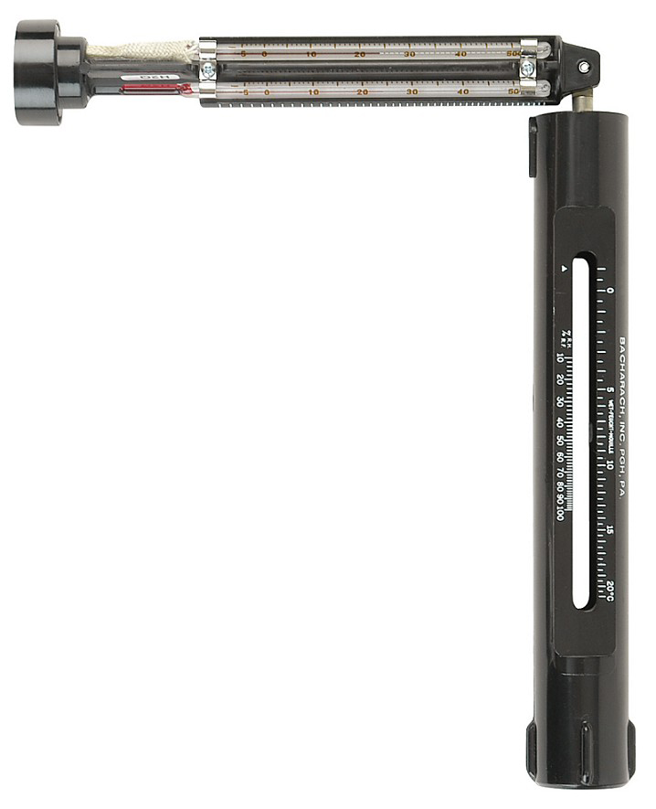
Typical manual Psychrometer
The current barometric pressure also has a small effect on the results so, to refine the result, measure the pressure and enter it into the %RH equation 14 where P is the pressure in kiloPascals (kPa), Td is the dry bulb temperature in ºC and Tw is the wet bulb temperature in ºC and e is the “natural” exponent value:
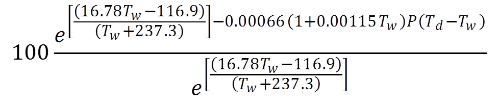
The equation can be broken down into simple steps:
| 1. | The barometric pressure (P) is assumed to be: 101.3 kPa |
| 2. | A conversion factor is calculated: A = 0.00066(1.0 + 0.00115 Tw) |
| 3. | The saturation vapor pressure is calculated at temperature Tw: |
| eswb = e[(16.78 Tw – 116.9)/(Tw + 237.3)] |
| 4. | The water vapor pressure is calculated: ed = eswb – A P (Td - Tw) |
| 5. | The saturation vapor pressure is calculated at temperature Td: |
| esdb = e[(16.78 Td – 116.9)/(Td + 237.3)] |
| 6. | The % RH is then calculated: RH = 100(ed/esdb) |
Aluminum Oxide Capacitive Sensor:
This sensor, like others, has electrical properties that change as function of humidity. It is sensitive to the water vapor pressure so more calculations are required to convert the measurement into relative humidity. The actual conversion equation is provided by the manufacture of this type of sensor.
Because it is sensitive to water vapor partial pressure, it is a good choice for moisture detection in natural gas lines and other industrial atmospheres. This sensor type must be kept dry and the gases being sampled must be clean and free of solids, which can harm the sensor.
To complete the calculation, atmospheric pressure must be accurately measured. This sensor type can also take a long time – up to 24 hours – to stabilize.
Polymer Capacitive Sensor:
The most popular relative humidity electrical sensor, this device actually changes its capacitance as a function of Relative Humidity, about 0.2pF to 0.5pF per 1%RH. Again, the manufacturer provides details on converting this capacitance change to %RH. Polymer capacitive sensors are very dependent on the temperature; however temperature is one of the easiest measurements to take, so this does not present any issues.
Extremely small, this sensor type is well suited for low power, digital humidity and temperature meters often found in office and factory floor environments.
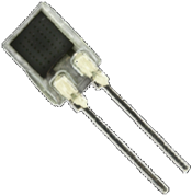
Typical Polymer capacitive sensor (magnified)
Human Hair Hygrometer (AKA: HHH):
Believe it or not, human hair has the unique property of expanding in high humidity and contracting in low humidity, about 2.5% from 0% to 100%. So a ten-inch long hair will stretch 0.25” from 0% to 100% RH. Though it is not recommended for measuring humidity in your factory, this method might make a great science fair exhibit project with your school-aged children!
Accuracy:
The readings given by a measurement device are said to be more accurate if there is a small (low) difference between those readings and the actual value of the parameter being measured. More accuracy is not necessarily gained just because there are a lot of digits in the reading. This just means there is more resolution and not more accuracy.
Resolution:
This is the total number of significant digits in the measurement value. More resolution is generally considered better, however, more digits do not equal more accuracy.
Repeatability:
No matter the accuracy or the resolution, when making the same measurement, is the result the same? The closer the readings of the same measurement are to each other (accurate or not), the better the repeatability.
Appendix F: Network
Dashboard:
.png)
| 1) | Data Graph: |
oCrosshair - The Data Graph displays a line connecting the points with their corresponding axis.
oRange Selector: The range selector is a tool for selecting ranges to display within the chart. It provides buttons to select preconfigured ranges in the chart (1, 3, 6 month etc). It also provides input boxes where min and max dates can be manually input.
oPrint and Download current graph view - allows the currently data displayed on the graph to be printed or saved (PNG Image, JPEG Image, PDF Document, or SVG Vector Image).
oNavigator - Displays a view of the entire data set. It provides tools to zoom in and out on parts of the data as well as panning across the dataset.
oScrollbar - Offers a means of panning over the X axis of a chart.
| 2) | Status (Real-Time): |
oCurrent RH & Temperature
oCurrent Mode:
▪SmartDRY™
▪SmartBAKE™ – Settings for J-STD or Manual Bake
oEvents:
▪Power on/off
▪Regenerate
▪Recovery
▪Door Activity (Open/Close) - This icon is also displayed on the Data Graph.
▪Door Alarm
▪Temp Alarm Bake
▪RH Alarm Bake
▪Temp Alarm Dry
▪RH Alarm Dry
▪Sensor Fault
▪Dryer Module Fault
▪Bake Heater Fault
Settings:
|
The Setting are a current snap shot of the cabinet settings. All changes to the cabinet settings have to be done from the Main Display. |
.png "Important Information")
.png)
| 1) | SmartDRY™ Settings: |
oRH - Displays the RH setpoint.
oAlarms - Displays any configured Alarms.
| 2) | SmartBAKE™ Settings: |
oSmartBAKE™ - Displays the settings for baking.
oAlarms - Displays any configured Alarms.
| 3) | Other Settings: |
oDate/Time - Displays the options for the date and time settings.
oData Logging - Displays the log interval when the unit records data.
oSensor - Displays the sensor type, Serial number and configuration.
oDoor Condition - Indicates if the Dashboard displays door notification.
oUnits - Displays the temperature units.
oNetwork - Displays the network IP Address, Subnet Mask and Gate way of the network that the cabinet is connected to.
Setup:
| 1. | Connect the ECD SmartDRY™ Cabinet to the Network via cable. The Cabinet acquires an IP Address from the Network. This will then be the URL Address for the SmartDRY™ Network. |
| 2. | Get SmartDRY™ IP address assigned by your Network. |
| a. | From the ECD SmartDRY™ Control Panel: |
| i. | Select Menu > Other Settings. |
| ii. | Scroll down to the Network Menu and Press OK. |
| iii. | Log and use the assigned IP address as the web address for your web browser to access SmartDRY™ Network. For example: http://10.1.1.999. |
Viewing initial SmartDRY™ data:
| 1. | On initial load of your SmartDRY™ Network using your SmartDRY™ IP address, you’ll be able to view current state of your SmartDRY™ Cabinet. |
| a. | Graph: |
| i. | Display RH, Temperature, Door Activity Graph. |
| b. | Real Time Status |
| i. | RH, Temperature, Door Activity. |
| ii. | Color Indicators: (Red, Yellow, Green, White) |
| iii. | Events: |
| 1. | Door Open |
| iv. | ECD SmartDRY™ Status and Settings: |
| 1. | SmartDRY™ |
| 2. | SmartBAKE™ |
| v. | Alarms |
| vi. | Fan and Desiccant Indicators |