The installation of the ECD SmartDRY™ Cabinet may be performed by the end user. Local, city, county, or other jurisdictions may govern the use of this equipment. If you have any questions about local requirements, please contact the appropriate local agency.
The ECD SmartDRY™ Cabinet is intended for indoor use only, at room temperatures between 15°C and 35°C, at no greater than 80% relative humidity (at 25°C) and <2, 000 meters (6,561ft) elevation.
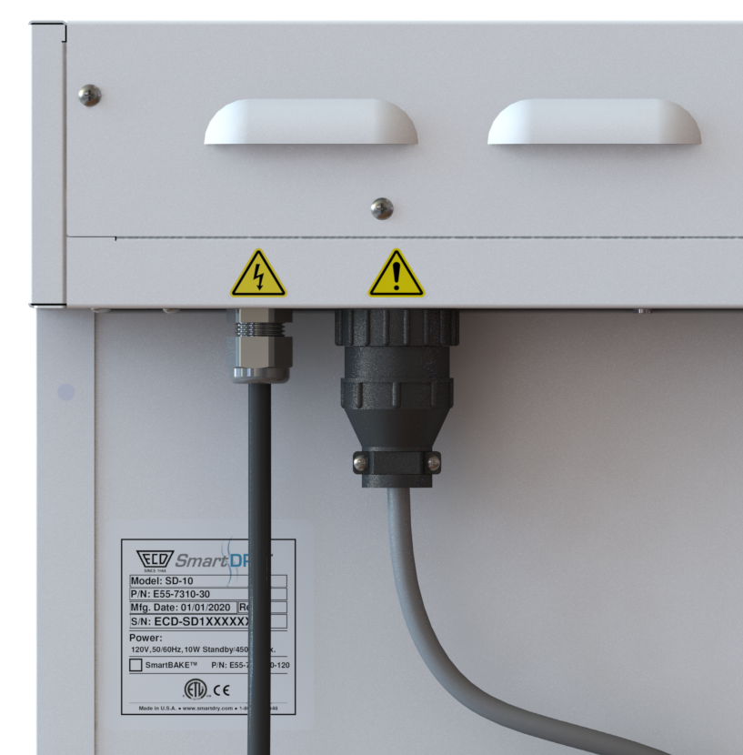
5.1 Power Source
The power requirements are listed on the cabinet serial number label. The supply voltage should not vary more than 10%.
|
Position the unit to allow user access to the power cord for mains disconnect. |
.png)
|
PLUG THE UNIT INTO A PROPERLY GROUNDED AND RATED RECEPTACLE OF THE CORRECT TYPE. THE VOLTAGE AT THE RECEPTACLE SHOULD NOT VARY MORE THAN 10% FROM THE LISTED RATING. |
5.2 Location
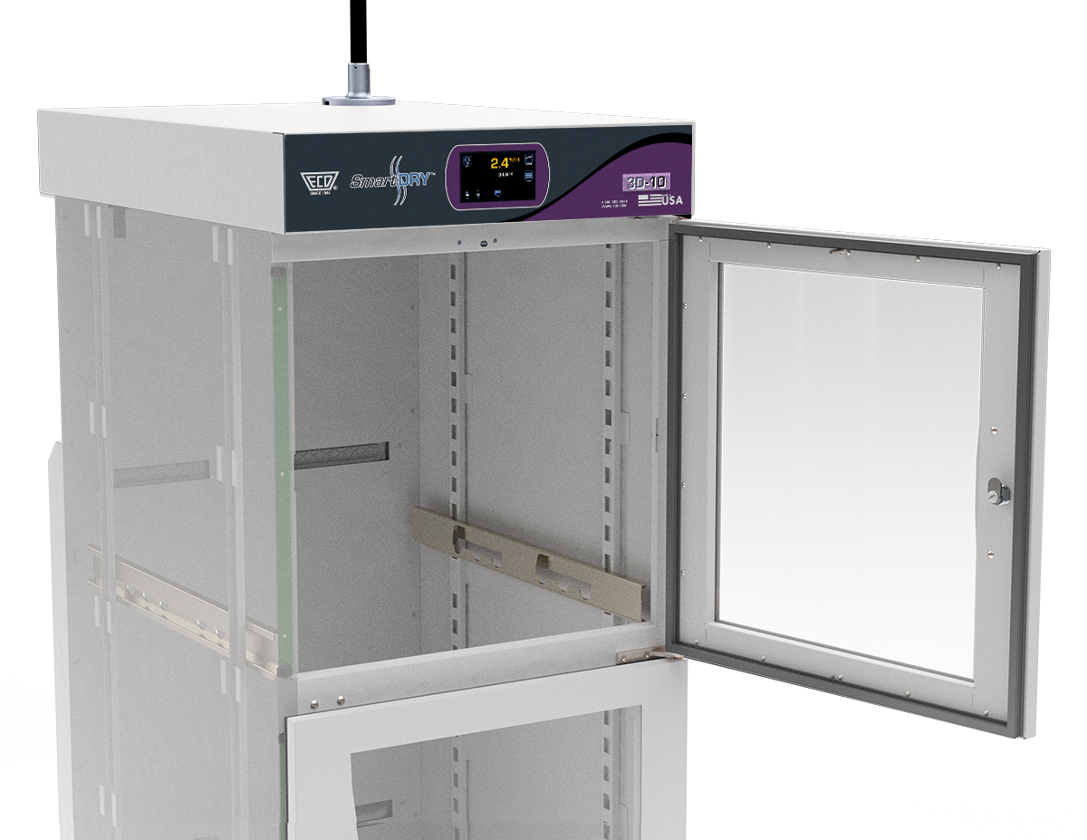
When selecting a site for the Cabinet, consider conditions which may affect performance, such as heat from radiators, ovens, production equipment, etc. Avoid direct sun, fast-moving air currents, heating/cooling ducts etc. To ensure air circulation, allow a minimum of 75 mm (3”) between the unit and any walls or partitions which might obstruct free air flow.
|
Position the unit to allow user access to the power cord for mains disconnect. |
|
|
-5.png)
-4.png)
|
MODEL 3D-10 SHOWN AS AN EXAMPLE. THE MINIMUM DISTANCE SPECIFICATION APPLIES TO ALL CABINET MODELS. |
.png)
|
To avoid over heating or risk of fire, do not block the dryer unit vents. |
5.3 Lifting and Handling
Cabinets are heavy and care should be taken to use appropriate lifting devices that are sufficiently rated for the load. Cabinets should only be lifted from their bottom surfaces. Door handles, enclosures and cabinet overhangs are not adequate for lifting or stabilization. The cabinet should be completely restrained from tipping during lifting or transport. Shelves should be removed and doors locked in the closed position before and during transfer to prevent shifting and damage.
5.4 Leveling
The cabinet should be placed on a level a solid, level surface. The wheels should be locked once in place to prevent movement.
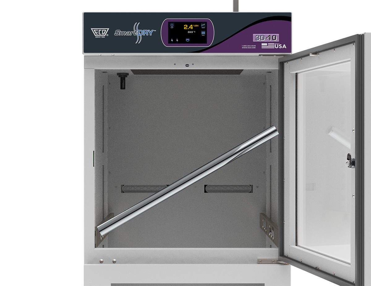
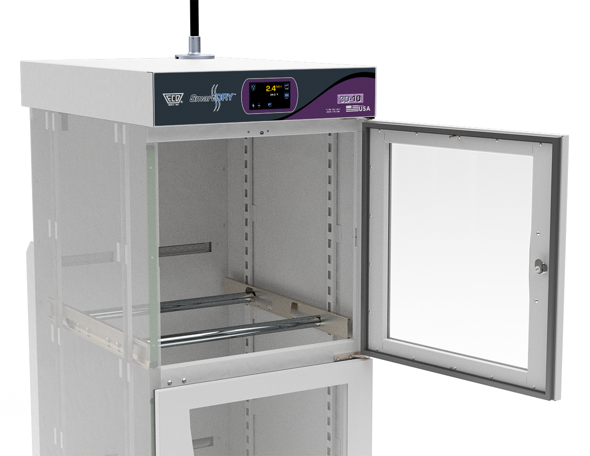
5.5 FILIMENT REEL RACK Placement
Cabinet Filiment Reel Racks are held in place on each side by a support bracket that slips into pre-cut slots. The support brackets are symmetrical and can be used to support either the left or right side of the filiment reel rods. Slots are pre-cut to prevent blocking of air vents and LED lighting in addition to fitting most common reels; place as needed to meet your needs.
To install:
| 1) | Open an cabinet door. |
| 2) | Insert the support brackets into the desired location of the tracks making sure they are both on the same track notch and secure. |
| 3) | Tilt the filiment reel rods at a slight angle, and insert through the cabinet door and place on the installed support brackets. |
|
To avoid damage to the cabinet LED's or the cabinet, when removing the filiment REEL RODS from it must be tilted enough to avoid contact with any obstacle. |
|
|
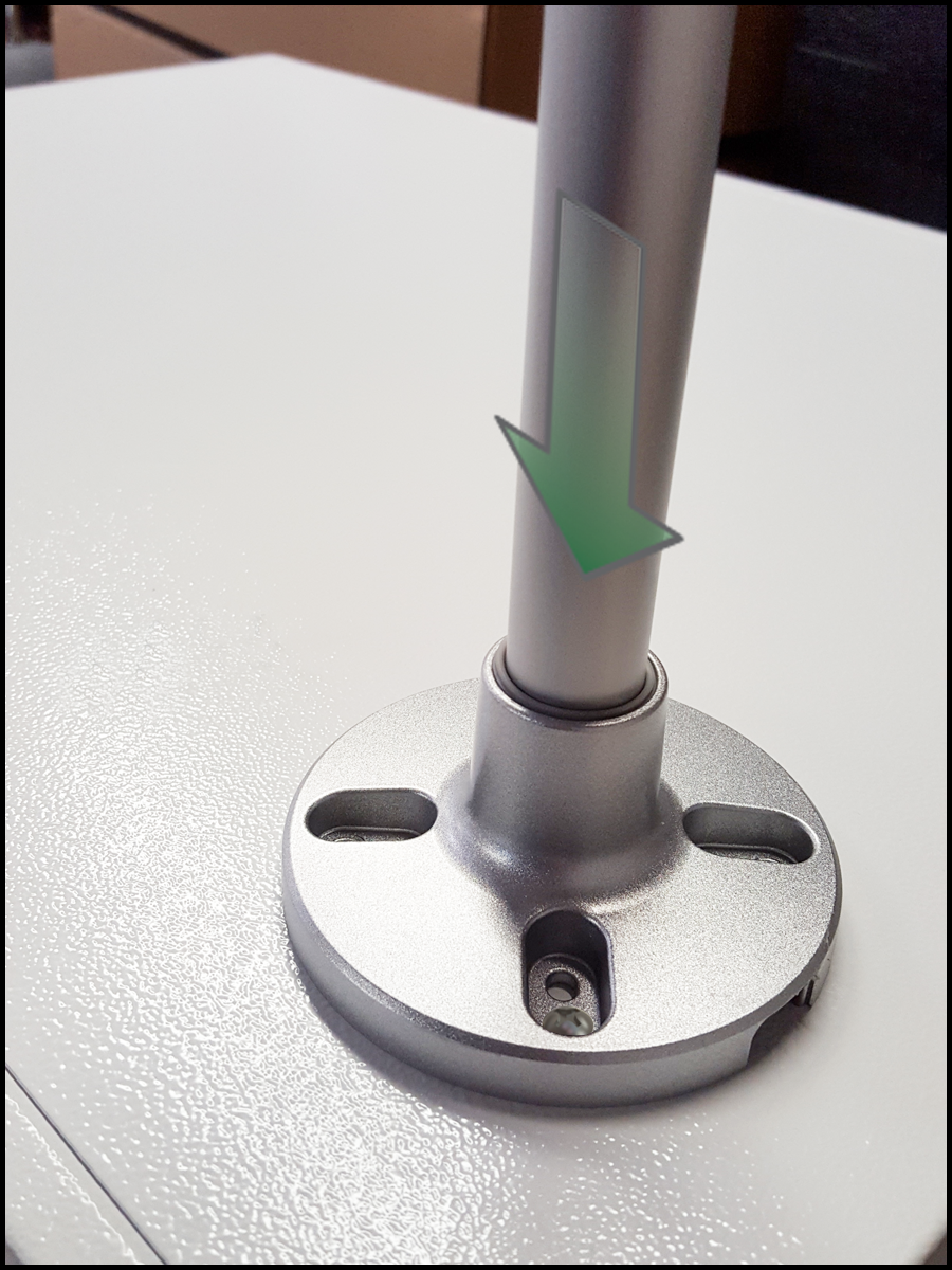
5.6 LIGHT TOWER (OPTIONAL)
The Light Tower is mounted with provided hardware to 4 pre-drilled holes in the control chassis cover.
To install:
| 1) | Remove any packaging. |
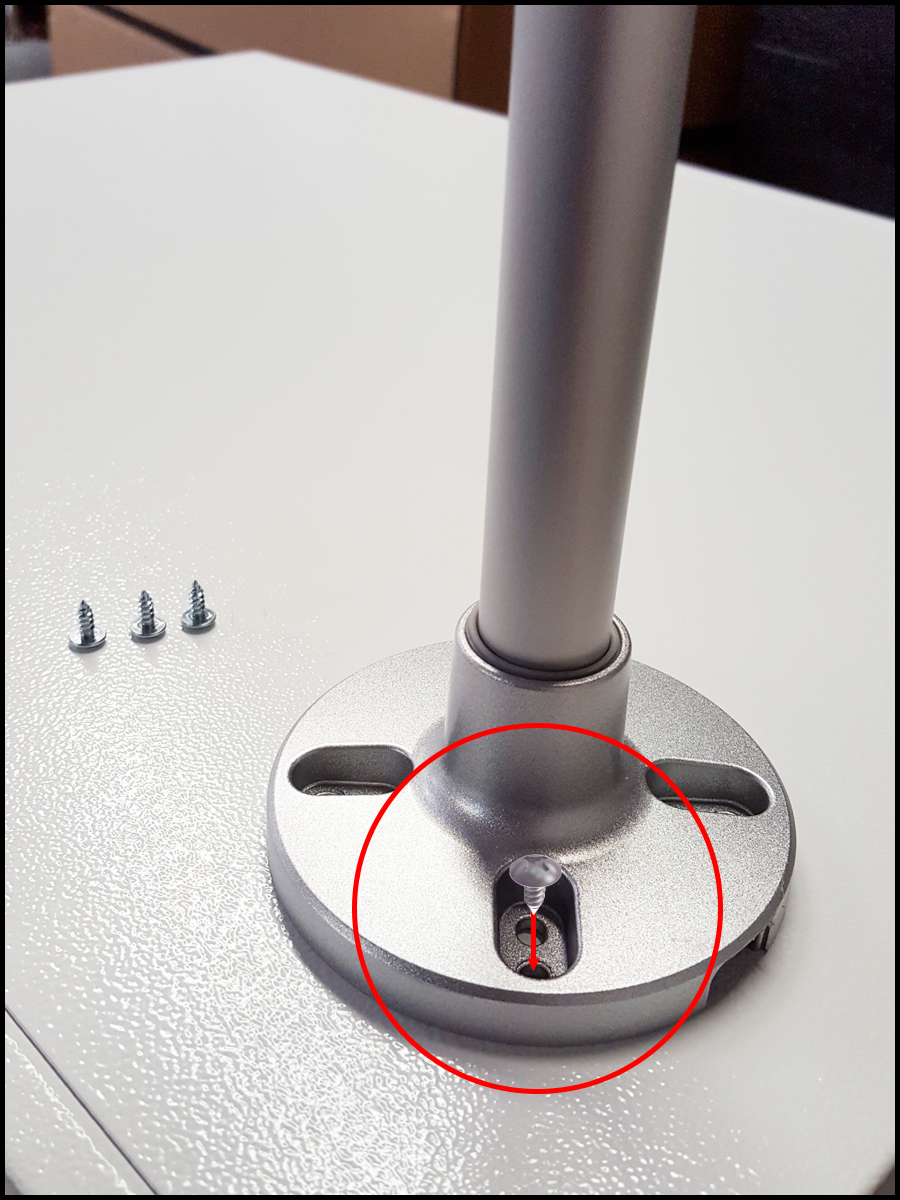
| 2) | Slide the Light Tower cable thru the mounting bracket until the metal post of the light tower is fully seated into the bracket. |
|
IF YOU WANT TO SECURE THE LIGHT TOWER TO THE MOUNTING BRACKET, REMOVE THE BRACKET FROM THE CONTROL CHASSIS COVER AND MOUNT THE BRACKET TO THE LIGHT TOWER WITH THE PROVIDED SCREWS.
RE-MOUNT THE LIGHT TOWER TO THE CONTROL CHASSIS COVER WITH FOUR SELF TAPPING SHEET METAL SCREWS (#6 X 3/8").
|
.png "Important Information")